Thursday, December 21, 2006

eQuest Boiler Curve Example

Topic: Efficiency performance curves published by equipment manufacturers may not be in a format helpful for energy modeling. This example presents a manufacturers condensing boiler, and derives a set of data points to which a curve can be fit using DOE2 routines.

The following efficiency curve is published by Aerco, representing the thermal performance of KC-1000 Series condensing boilers; the color annotations have been added by the author:

(click on the image to see a larger version)

The three curves on the chart represent firing rates of 37.5%, 75% and 100% from top to bottom. Thermal efficiency can be read on the vertical axis by knowing the firing rate and return water temperature. eQuest/DOE2 however requires input data points for boiler performance curves to be in entering water temp / leaving water temp / heat input ratio (inverse of thermal efficiency) format.

According to the chart, thermal efficiency is independent of both flow and supply water temperature, so the firing rate data curves and entering water temperature points should indicate efficiency regardless of the infinite combinations of flow rates and supply temperatures possible. This produces however, essentially an infinite number of efficiency curve solutions. To solve this problem, we must temper the manufacturer's published data with a measure of sound engineering judgement.

(click on the image to see a larger version)

Realizing that a low firing rate should occur at low load conditions, a high firing rate at high load conditions, and a mid firing rate somewhere in between, let us make the careful assumption that a high firing rate will result in a 40° (100%) ΔT, a mid firing rate in a 30° (75%) ΔT , and a low firing rate in a 15° (37.5%) ΔT across the boiler.

Using these ΔT's, we can now compute a corresponding leaving water temperature for each of the data points on the chart, except for the five at the extreme right. Efficiency is poorest here as entering water temperature approaches that of leaving water temperature. So dispensing with these data points should not detract much from the resultant accuracy of the curve fit, since our control system and operational sequencing should not allow the equipment to operate in this regime anyway.

Following is the BDL code required for a binomial quadratic curve fit of the Aerco KC-1000 condensing boiler's heat input ratio in terms of entering and leaving water temperatures:

"Aerco-KC1000-HIR" = CURVE-FIT
TYPE = BI-QUADRATIC-T
INPUT-TYPE = DATA
INDEPENDENT-1 = ( 80, 80, 80, 100, 100, 100, 120,
120, 120, 140, 140, 140, 160 )
INDEPENDENT-2 = ( 95, 110, 120, 115, 130, 140, 135,
150, 160, 155, 170, 180, 175 )
DEPENDENT = ( 1.010, 1.070, 1.093, 1.058, 1.111, 1.117, 1.093,
1.136, 1.143, 1.130, 1.143, 1.149, 1.136 )


In addition to efficiency, another significant item that needs to be changed when comparing firetube to condensing boilers parametrically is the standby time, which figures directly into standby losses as a percentage of full load capacity.

For example, the default STANDBY-TIME of 0.027 (corresponding to a standby loss of 2.7%) in eQuest may be a bit high for larger firetube boilers; check the manufacturer's data as relative standby losses tend to decrease as boiler size increases. However, condensing boilers do not need to stay warm to avoid thermal shock; hence standby loss factors are on the order of one-tenth that of firetube boilers.

Per Cleaver-Brooks, the standby loss on a 1,000,000 BTU per hour Clearfire condensing boiler is 1810 BTUH or 0.1810%, which translates to a STANDBY-TIME of 0.00181 factor.

Wednesday, December 20, 2006

eQuest Detailed Editor Checklist

Topic: Miscellaneous notes for using eQuest in detailed edit mode.

eQUEST DETAILED EDITOR

Post-Wizard Shell Editing

  • Add note about saving wizard snapshot...
  • Add any missing upper level shell exterior walls.
  • Import the following BDL code fragments from the network library:
    • H:\eQuest\Library\Envelope_WSEC_Compliant.inp

      and, if doing an ELCCA...

    • H:\eQuest\Envelope_ELCCA_Prescriptive.inp
  • Assign the baseline envelope shell components corresponding to WSEC Compliant
  • Remove the roofs of lower-level shells where upper level shells are placed.
  • Verify that the floors of the upper level shells are adiabatic; it may be helpful to separate the shells by temporarily specifying z-coordinates of 100 feet or more between them.
  • Define air-walls between zones where appropriate.
Post-Wizard Space Editing
  • Specify the number of people per square foot under the 'Basic Specifications' tab of the Space Properties dialog box for each space.
    • Do this or else eQuest will calculate the people density for you, and it will be low
    • Specify 31 persons for classroom, multiply the number of classrooms in the space, and divide by the total square footage of the space.
    • Specify the maximum number of occupants of the school for gymnasiums, cafeterias, auditoriums and multipurpose rooms; scheduling will account for daily diversity.
    • Specify 75 SF/person for administrative areas and libraries
    • Specify 1000 SF/person for restrooms, corridors, and support areas; this will help to moderate outside air demands.
    • Note that when the area per square foot is specified, and the number of people are reset to the default or 'green' value, this default value is calculated by eQuest to be the total area divided by the people factor per square foot.
    • Check daylighting sensors for location and orientation; adjust as required.
Renaming Spaces, Zones and Systems

Renaming shells, spaces, zones and systems to improve the interpretability of simulation output and improve the accuracy of internal load factor assignment is best done at the beginning of detailed edit mode. The 15 minutes to half-hour spent doing this will pay great dividends going forward, for even modestly complex projects.
  • Rename Shells: By default all shells are named "ELn Ground Flr", where "n" is the sequence number of the shell in the order in which it was added to the project. Rename the shell to something more descriptive like "EL1 Bldg 100" or "EL2 Second Floor" while retaining the shell designation prefix, which is used throughout the project by eQuest for the automatic naming of related components.
  • Renames Spaces: In Component Tree view, next rename spaces for each shell to something more descriptive. For example, a group of classrooms may be automatically named "EL2 North Perim Spc (G.N1)"; rename to something like "EL2 Classrooms North Space", retaining the shell designation prefix and adding the "Space" suffix.
  • Renames Zones: Switch to the Air-Side HVAC tab. Starting at the top of the component tree, double-click on each zone and rename it corresponding to its space. For instance, continuing the previous example, rename "EL2 North Perim Zn (G.N1)" to "EL2 Classrooms North Zone"; note that the corresponding space is listed in the properties dialog box of the zone for easy reference.
  • Renames Systems, Single-Zone: For packaged single zone systems, rename the system to correspond to the zone. For instance, continuing the previous example, rename "EL2 Sys2 (PSZ) (G.N1)" to "EL2 Classrooms North Sys"; note that the corresponding zone is listed in the component tree view below the system for easy reference.
  • Renames Systems, Multi-Zone: For multiple zone systems, rename the system to a using a general geographic designation. For instance, continuing the previous example, if the system type of "EL2 Sys2 (PSZ) (G.N1)" is changed from 'packaged single zone' to 'packaged multizone', the automatically assigned system name will not be changed by eQuest. Hence change the system name to something like "EL2 Multizone North System"; with the name selected to enable easy recognition when reading DOE2 reports.

Note: This needs to be integrated into a comprehensive sequential detailed edit checklist.


Post-Wizard System Editing

  • Specify minimum CFM per square foot values for each system under the 'Flow Parameters' subtab of the 'Fans' tab of the Air-Side HVAC System Parameters dialog box for each system.
    • Do this or else eQuest will calculate the value for you, and it will be low
    • Specify 1.3 CFM/SF for classroom, administrative and other high-occupancy areas
    • Specify 1.0 CFM/SF for gymnasiums, cafeterias, multipurpose rooms and corridors
  • For cooling-only systems, remove the drybulb economizer lock-out. The default is 65°F, which is OK if mechanical cooling is provided. However to reduce the number of unmet load hours in natural, displacement and conventional ventilation systems without mechanical cooling, this constraint should be removed.
Parametric Runs
  • Using spreadsheet view, set Daylighting to 'No' for all zones, for the baseline case.
  • Create the following four parametric runs in the "working copy" of the project after it has been saved with all shell & envelope modifications captured:
    • Envelope Improvements
    • Lighting Improvements
    • Daylighting
    • Demand Ventilation
  • Others may be added, specific to each of the particular systems studied, after the working copy of the project is saved in system-specific versions.
  • Any 'Appendix G' baseline generally does not require parametric runs. [more detail]
Note: This is a work-in-progress procedure, additional details forthcoming time permitting

Doors & Windows
  • Generally custom door and window placement should be accomplished in Wizard mode. The following procedures may be useful when doors and windows need to be defined in detailed edit mode.
  • Assure that the total area of the windows does not exceed total wall area, else an error will result. This is problem can arise particularly on all glass stair towers, entryways, and corridors where the wall is essentially all glass. To prevent this from happening, the following user expressions may be used for positioning and defining the width and height of "glass wall" windows:
X = {PARENT("WIDTH")*0.025}
Y = 0
HEIGHT = {PARENT("HEIGHT")}
WIDTH = {PARENT("WIDTH")*0.95}
  • The following expression may be used to center doors and windows in the parent wall:
X = {PARENT("WIDTH")/2-LOCAL("WIDTH")/2}
  • The following expression places doors or windows centered on the one third or two thirds points from the origin of the parent wall, respectively:
X = {1*PARENT("WIDTH")/3-LOCAL("WIDTH")/2}
X = {2*PARENT("WIDTH")/3-LOCAL("WIDTH")/2}
  • Use the following expression to create windows of a fixed height as wide as the parent wall:
WIDTH = {PARENT("WIDTH")}
  • Use the following expression to right-justify doors and windows:
X = {PARENT("WIDTH")-LOCAL("WIDTH")}
  • Editing Windows Frame and Spacer:
    • In order to eliminate windows frame. first go to the Building Shell mode and click on Spreadsheet.
    • While on the Component Tree tab, click on one of the windows (i.e E1 South Win).
    • Change the Frame Width of the window to default (zero) - this can be done easier and faster using multi-edit if you working with thousands of windows.
    • Next, change the frame spacer type from the default 'Aluminum' to 'Insulated'
    • WRITE-UP MULTIEDIT METHOD USING REGULAR EXPRESSIONS.

Schedules

Follow this link for schedule sharing. Implement common schedules now so you don't have to do it 3 or 4 times going forward.


Fan Schedules

After implementing the schedules sharing, the "Fan Schedules" in the Fan Power and Control tab needs to be adjusted. The Cooling should be set automatically to ESM Fan Sch after the schedule input; however, the Exhaust tab will still be empty. ESM Exhaust Fan Sch need to be selected in the Exhaust tab.


Simulations
  • Change the TITLE, LINE-1 parameter at the beginning of each baseline INP file.
    • Rename systems appropriately (e.g. PVVT, PSZ etc.) to for instance, GSHP using MultiEdit (expound).
    • Noted if system name is changed via GUI or inp, any reference to the system name in the parametric run definition (.prd) file must be changed manually, most easily via text editor.
  • Run trial simulation for each system type.
    • Eliminate any errors (e.g. 'LOOP has ZERO FLOW') to obtain valid trial simulations.
    • Examine .SIM output file for each valid trial simulation, and update .INP file to eliminate warnings and errors.
      • Exceptions: __ warnings are insignificant (list).
  • Run the 'Annual Energy Consumption by Enduse Report' for the baseline for each system (need graphic).
    • The lighting, misc. energy usage, ventilation, domestic hot water and ___? should all be the same.
    • If not, there is a variance in the energy densities or scheduling...correction needed.

    Friday, December 15, 2006

    eQuest Graphical Editor Notes

    Topic: The eQuest graphical editor is simple, but the documentation for it is difficult to locate. This post is a quick-reference guide.

    Use the following list of keyboard and mouse combinations within the eQuest graphical model editor window:

    • 'W' changes to wireframe view mode
    • 'S' changes to surface view mode (default)
    • Ctrl+ left mouse button allows 3D model orbiting with the mouse
    • Ctrl+ right mouse button allows 3D model zooming with the mouse
    • Right-clicking with the mouse deploys a context menu with additional options
    If the building model "disappears" in the process of orbiting and zooming, click out of the 'Building Shell' on the toolbar, for instance to 'Internal Loads', then back to 'Building Shell'. Then right-click within the graphical display window and select 'Reset Camera'.

    Thursday, December 14, 2006

    Contents of eQuest Project/Runs List

    Topic: In Reports Output mode, what controls the contents of the list in the Project/Runs tab, and how can that list be edited?

    The Project/Runs list is populated by the simulation results that are contained in the "Projects" folder of your eQuest program directory.

    If it is desired to prevent items from showing up, one alternative is to make a new folder (for example, "Projects Archive") in the eQuest program file directory and move the unused files to that folder.

    For eQuest projects stored in a network folder, the results viewer will show the results for all projects in the "Projects" folder of eQuest along with all of the results that are in the folder for the currently active project. Thus copies of known good baseline projects may be stored locally, for use in comparison to network projects under development.

    It may also be necessary to edit feed the .pdh file with a text editor. For example, if parametric runs are renamed, the .pdh file may continue to list the old names; in this case the old names contain 'DCV' resulting in an erroneous project/runs list:

    1,"Garfield ES - GSHP" ,
    1,"4 - Classroom, Admin & Library DCV" ,"Garfield Elementary - GSHP - 5" ,1172020623,
    1,"3 - Gym & Cafeteria DCV" ,"Garfield Elementary - GSHP - 4" ,1172020604,
    1,"2 - Lighting Improvements" ,"Garfield Elementary - GSHP - 2" ,1172020568,
    1,"1 - Envelope Improvements" ,"Garfield Elementary - GSHP - 1" ,1172020551,
    1,"Baseline Design" ,"Garfield Elementary - GSHP - Baseline Design" ,1172020536,
    1,"4 - Demand Ventilation" ,"Garfield Elementary - GSHP - 4" ,1172012402,
    1,"3 - Daylighting" ,"Garfield Elementary - GSHP - 3" ,1172012385,
    -1,

    Simply delete the lines containing old parametric run names from the .pdh file, replacing them with the lines containing the new names:

    1,"Garfield ES - GSHP" ,
    1,"4 - Demand Ventilation" ,"Garfield Elementary - GSHP - 4" ,1172012402,
    1,"3 - Daylighting" ,"Garfield Elementary - GSHP - 3" ,1172012385,
    1,"2 - Lighting Improvements" ,"Garfield Elementary - GSHP - 2" ,1172020568,
    1,"1 - Envelope Improvements" ,"Garfield Elementary - GSHP - 1" ,1172020551,
    1,"Baseline Design" ,"Garfield Elementary - GSHP - Baseline Design" ,1172020536,
    -1,

    Be sure to do this with eQuest closed; upon reopening eQuest the project/runs list should now meet or exceed expectations.

    Tuesday, December 12, 2006

    eQuest Analysis Project Structure

    Topic: How best to structure an eQuest analysis project?

    The following is a suggested file naming convention for eQuest analysis projects:

    • project_name_baseline
    • project_name_baseline_envelope
    • project_name_baseline_electrical
    • project_name_alternate_#1
    • project_name_alternate_#2
    • project_name_alternate_#n
    In order to work with the eQuest limit of analyzing up to five ECM groups side by side, the following procedure is suggested for separating envelope and electrical ECM groups from mechanical ECM group alternates.
    • Fully develop the mechanical baseline run analysis without ECM's, using code-minimum windows, walls and roofs.
    • Save as the envelope and electrical options as shown in the file naming convention above.
    • Add proposed envelope and electrical ECM's to the respective analysis run, and
    • Determine the recommended ECM package for each using the baseline mechanical equipment.
    • Analyze the mechanical ECM groups in the baseline and alternates, with the selected envelope and electrical ECM packages "rolled up", into a single ECM group.

    Monday, November 20, 2006

    Architectural ELCCA Questionnaire

    Topic: Standard questions to the project architect from the ELCCA analyst to complete the ELCCA workplan and report.

    1) In general, State of Washington publicly-funded projects require an ELCCA if the project exceeds 25,000 ft.² or 50% of the total value of the facility.

    • Public school projects which exceed 25,000 ft.² but not 50% of the total value the facility are excepted, and may file a PFEC only.
    • See complete requirements in the 2005 ELCCA Guidelines.
    2) WSEC values shown below are from the 2006 Washington State Energy Code
    3) ELCCA values shown below are from the 2005 ELCCA Guidelines.

    4) Reconcile any changes with the Architectural PFEC Questionnaire post.

    ELCCA Workplan:

    Note to the Analyst: Upon project initiation, cut-and-paste following questions to the body of an e-mail to the architect. Include copies of the LEED Scorecard and the Environment Design Considerations form as attachments, which you have completed to the best of available knowledge. These forms can be found by searching the index of this blog under 'Templates'.
    • Building or project occupancy, number of persons
    • Building or project size, square feet.
    • Percent of building or project that is new
    • Percent of building or project that is remodel
    • Building-only cost estimate
    • Site cost estimate
    • Owner's project manager and telephone or e-mail
    • Estimated VE date
    • Estimated bid date
    Walls
    • Are the wall insulation systems between-studs batt, external rigid, or a combination of both?
      • For all combination systems, please provide sketch.
    • Do all of the anticipated wall constructions meet minimum Washington State Energy Code (WSEC) values? For example, are there any uninsulated masonry walls that may need to be compensated for elsewhere?
      • Net effective WSEC minimum values in Climate Zone 1 (Western Washington) are approximately R-17 for wood framed wall, R-10 for metal framed wall, and R-7 for masonry wall assemblies.
      • Net effective WSEC minimum values in Climate Zone 2 (Eastern Washington) are approximately R-17 for wood framed wall, R-12 for metal framed wall, and R-9 for masonry wall assemblies.
    • Will any of the anticipated wall constructions meet or exceed ELCCA prescriptive values?
      • Net effective ELCCA prescriptive values are approximately R-12 for framed or 'light' wall, and R-10 for 'mass block' or masonry wall assemblies in both climate zones.
      • Note that per the WSEC, all metal framed walls in Climate Zone 2 and all wood-framed walls in both climate zones meet and exceed ELCCA prescriptive values, respectively.
    Roofs
    • Do all of the anticipated roof constructions meet minimum WSEC values?
      • WSEC minimum values in Climate Zone 1 are approximately R-22 for most commercial and institutional roofs.
      • WSEC minimum values in Climate Zone 2 are approximately R-26 for most commercial and institutional roofs.
    • Will any of the anticipated roof constructions meet or exceed ELCCA prescriptive values?
      • ELCCA prescriptive values are approximately R-30 for roofs in both climate zones. An exception is listed for batt insulation applied on the underside of the roof deck between roof joists; in this case R-38 is required to compensate for the thermal conductance of the joists.
    Glazing
    • What are the approximate areas or percentages of vertical and horizontal glazing?
    • Is the building anticipated to have greater than 30% glazing?
      • Exceptions are listed for buildings with greater than 30% glazing, and those heated exclusively via electric resistance.
    • Will all of the anticipated glazing assemblies meet minimum WSEC values?
      • In both climate zones, most vertical glazing (windows & doors) are required to have a maximum 0.55 U-value and 0.45 maximum Solar Heat Gain Coefficient (SHGC).
      • Most horizontal glazing (skylights) are required to have a maximum 0.70 U-value and 0.40 maximum SHGC.
    Doors
    • Opaque doors are required by the WSEC to have an R-value of approximately 2 (U-0.60 maximum) in both climate zones. Please advise if doors are not anticipated to meet these requirements.
    ELCCA Report:

    • xx
    • xx
    • xx
    • xx
    • xx

    Friday, November 17, 2006

    Mechanical ELCCA Questionnaire

    Topic: Standard questions for the mechanical engineer.

    ELCCA Workplan

    • Is there any documentation available from the eco-charette?
    • Is there a LEED 2.2 checklist available reflecting direction from the eco-charette?
    • What 'High-Performance' system would you like to model? Recommend ground-source heat pump, as this system also qualifies as the 'Renewable' system.
    • If not ground-source heat pump for High-Performance system, than what system would you like a model as the 'Renewable' energy system? Systems qualifying as 'Renewable' in the past include displacement ventilation, and any system coupled with natural ventilation.
    • What other two systems would you like a model? Suggestions include:
      • Water source heat pump.
      • Displacement ventilation.
      • Centralized air handler with zone duct coils.
      • Two-pipe or four-pipe blower coil with VAV or FPVAV.
    • Is there a kitchen in this project, and if so is it primarily gas or electric?
    • Do you anticipate the domestic hot water system to be gas or electric?

    Thursday, November 16, 2006

    Electrical ELCCA Questionnaire

    Topic: Standard questions to the electrical engineer from the ELCCA analyst to complete PFEC form, the ELCCA workplan, and the ELCCA report.

    Note 1) WSEC values shown below are for the 2006 Washington State Energy Code
    Note 2) ELCCA values shown below are for the 2005 ELCCA Guidelines
    Note 3) The functional area list will answer for most schools; edit as required
    Note 4) Code maximum power density is less than or equal to ELCCA prescriptive for administrative, multipurpose, cafeterias, gymnasiums, and auditorium areas.

    PFEC Form:

    Note to the Analyst: The following questions found on the PFEC may be answered by the electrical drawings, or may require the input from the electrical engineer.

    • Fixture description including lamp and ballast type for the following functional areas:
      • Classrooms
      • Administrative
      • Multipurpose/gymnasium
      • Corridor & commons
    • If available, obtain copies the NREC forms and the luminaire schedule from the electrical engineer; these will help to answer quantitatively most of the electrical questions on the PFEC.
    ELCCA Workplan:

    Note to the Analyst: Upon project initiation, cut-and-paste following questions to the body of an e-mail to the electrical engineer. If a timely responses is not received, the workplan may be submitted using prescriptive values. However responses are required to the questions of this section in order to complete the ELCCA report. The workplan should be updated if the electrical engineers responses are at variance with the information submitted.
    • Fixture description including lamp and ballast type for the following functional areas:
      • Classrooms & learning commons
      • Administrative
      • Multipurpose/gymnasium
      • Corridors & restrooms
    • What are the design lighting densities in the following functional areas? (WSEC maximums/ELCCA prescriptives shown in parentheses):
      • Classrooms (1.2 /1.15 W/sf) :
      • Administrative (1.00 /1.10 W/sf) :
      • Multipurpose, cafeterias, gymnasiums, and auditoriums (1.0 /1.0 W/sf):
      • Corridors and restrooms (0.80 / 0.70 W/sf) :
    • If daylighting is provided, will control be zone switched or continuous dimming?
    • If the lighting densities in classrooms and corridors exceed ELCCA prescriptives, we must evaluate two lighting alternatives.

      • Lighting Alternative #1:
      • Lighting Alternative #2:
    ELCCA Report:

    In addition to the information from the preceding section, request the following data from the electrical engineer when available for inclusion in the ELCCA report:
    • Lighting layouts
    • Luminaire schedule
    • Exterior lighting power, kW
    • NREC forms, if available
    • Emergency generator power, kW
    Some of the items above may not be available until near the end project, and thus will not be available if the ELCCA is to be submitted near the end of schematic design of during the design development phase.

    Wednesday, November 15, 2006

    Trace 700 Input Data

    Topic: Suggested standard input to be included in the appendix of the ELCCA report.

    In the "Input Data" appendix of the ELCCA, include the following reports as the when using Trace 700 as the analysis software:

    • Entered Values, Project Information
    • Entered Values, Room Information
    • Design Weather
    The following screen capture showed the reporting module dialog boxes; the first one is accessed from the "View/Entered Values" menu in the main program, and the second from the "File/Print" menu of the Libraries/Templates manager:

    Tuesday, November 14, 2006

    Trace 700 Output Data

    Topic: Suggested standard output to be included in the appendix of the ELCCA report.

    Include the following reports as the "output data" when using Trace 700 as the analysis software:

    • Energy Cost Budget, which compares all alternatives
    For each alternative, include:
    • Energy Consumption Summary
    • Equipment Energy Consumption
    • Monthly Energy Consumption
    • Monthly Utility Costs
    The above output data can be printed from the "Analysis" tab of the report module:


    Tuesday, November 07, 2006

    Standard Energy Efficiency Measures

    Topic: Energy Efficiency Measures (EEMs) that may prove cost-effective in the context of typical ELCCA projects.

    • Daylighting
    • Heat recovery
    • Envelope improvements from Code Minimum up to ELCCA Prescriptives
      • Roof
      • Wall
      • Window & door
    • Demand ventilation
      • CO2 zone sensor control for large volumes, or
      • Lighting occupancy sensor control for offices and classrooms
        • If the electrical engineer is providing occupancy sensors for lighting control in the classrooms and possibly office areas, then interlocking the outside air damper operation to close when the lights are commanded off is a relatively simple energy saver.
        • Estimating the value of this EEM is variable depending on the school -- obviously high schools and colleges with classrooms that aren't necessarily used all day will have a higher diversity and thus stand to save more energy.
        • However if electrical is providing the occupancy sensor, then the marginal cost of interlocking for HVAC control should be minimal.
        • Given actual elementary school schedules for assemblies, lunch hours, recesses, field trips, and early dismissal a potential for savings exists -- but quantifying it is little more difficult.
    • Improved boiler efficiency
      • Typically improved from an 80% baseline to 85% or 88%
    • Improved lighting utilization per unit area over code specified maximum

    Wednesday, November 01, 2006

    Using AutoCAD Building Systems for Area Takeoffs

    Topic: Using the eSpace/Space feature of ABS to simplify area takeoffs for energy analysis purposes.

    • xref all floors of the building background to a new drawing, called say "JOBNUM_Area_Takeoffs.dwg"
    • Use 'OT' to set osnap tracking on, 'OM' to add midpoints
    • Use the 'ES' macro to draw an eSpace element
    • Don't use eSpace arcs, will not import into eQuest correctly. Use line segments to approx. arcs.
    • 'GNP' for general noplot layer for construction lines
    • draw spaces to midpoint of walls
    • insert 'Area Takeoff' schedule
    • attach property set to spaces if required

    ...needs work

    Post text on ABS Exchange, link from here.

    Monday, October 30, 2006

    Washington State Utility Rates

    Topic: Provide quick access to current utility rates in Washington state.

    Notes:
    (1) PSE Electric Schedules: 7 Residential, 31 General Commercial
    (2) PSE Gas Schedules: 23 Residential, 31 General Commercial, 36 Special Educational

    Thursday, October 19, 2006

    eQuest Transfer Air and Other Notes

    Topic: Document notes from internal meeting on above referenced topic

    Friday, October 13, 2006

    Combining the High-Performance Building Alternative

    Note page 25 excerpted from Washington State ELCCA Guidelines, which documents the acceptable criteria for using one of the previously-studied alternatives as the High-Performance Building (HPB) alternative.

    According to the criteria, the HPB alternative may use ANY previously studied alternative, PROVIDED that it meets the energy savings goal of the LEED scorecard. IF the previously studied alternative will meet the energy goal only with a some modification (e.g. the addition of heat recovery and/or demand ventilation) THEN the MODIFIED ALTERNATIVE may be used as the HPB. However a modified alternative is still another alternative, and so must be analyzed equivalent to the others.

    Note that the HPB alternative does not necessarily need to be based on the 'Renewable' alternative. But 'waste heat recovery' can qualify many of the systems we design as renewable alternatives (see Table 4.3 the ELCCA Guidelines, at the top of page 25), and this feature will help significantly in attaining the LEED energy goal.

    So what is the 'energy goal' referred to by LEED as the benchmark criteria?

    The energy goal is defined per ASHRAE 90.1-2004 Appendix G as the energy savings required of the HPB over the Baseline Building (BLB):

    LEED 2.1 EAc1:

    1 Point New Buildings 10.5% Existing Buildings & Renovations 3.5%
    2 Points New Buildings 14% Existing Buildings & Renovations 7%
    3 Points New Buildings 17.5% Existing Buildings & Renovations 10.5%
    4 Points New Buildings 21% Existing Buildings & Renovations 14%
    5 Points New Buildings 24.5% Existing Buildings & Renovations 17.5%
    6 Points New Buildings 28% Existing Buildings & Renovations 21%
    7 Points New Buildings 31.5% Existing Buildings & Renovations 24.5%
    8 Points New Buildings 35% Existing Buildings & Renovations 28%
    9 Points New Buildings 38.5% Existing Buildings & Renovations 31.5%
    10 Points New Buildings 42% Existing Buildings & Renovations 35%


    Attaining LEED Silver requires 33-38 points on the LEED Scorecard; the ELCCA Guidelines further stipulate that no less than four points shall be earned from the 'Energy Optimization' portion of the scorecard for the HPB alternative.

    So, the bottom line is that the HPB alternative is required to show improved savings of 21% for new construction, and 14% for existing buildings and renovations over the BLB.

    Thursday, October 12, 2006

    ELCCA Templates

    Topic: Use modified templates to expedite the preparation of required forms.

    Templates use a "prior job" format to demonstrate what the completed form should look like, and a color key macros to simplify differentiation between changed and unchanged work.

    Note: The above link(s) are only valid within the HEI intranet. Firefox users install the "IE Tab Plug-in", then right-click the link and select "Open in IE Tab" from the context menu.

    Friday, October 06, 2006

    Energy Analysis Glossary

    CHP = Combined Heat and Power
    COP = Coefficient of Performance, ratio of energy output divided by energy input

    DER = Distributed Energy Resource

    EER = Energy Efficiency Ratio, the COP times 3.412
    EIR = Energy Input Ratio, the inverse of COP
    ELCCA = Energy Life Cycle Cost Analysis

    LEED Leadership Energy and Environmental Design

    NREC Non-Residential Energy Code

    WSSP Washington Sustainable Schools Protocol

    The Public Facilities Energy Characteristics (PFEC) Form

    Topic: The Washington State Facilities Energy Characteristics (PFEC) form is integral part of every ELCCA report.

    • For projects less than 25,000 sf, or where the renovations total less than 50% of the value of the facility, then the PFEC alone suffices to satisfy State of Washington Department of E&A Services energy analysis requirements.
    • Show common data required on the PFEC and NREC forms.
    Updated PFEC Template with improved formulas, comments, and color-coded data entry. [Note this linking to a local file doesn't seem to be working... investigate]

    Tuesday, October 03, 2006

    ELCCA Process Flow & Report Structure Diagrams

    Future Topic: Post a link to the ELCCA process flow diagram, generate an ELCCA report structure/outline diagram.

    Friday, September 29, 2006

    NREC Forms

    All non-residential building projects in the State of Washington as part of the permitting process need to submit Non-Residential Energy Compliance (NREC) forms. NREC forms are required for mechanical systems, building envelope, and lighting systems.

    Monday, September 25, 2006

    eQuest Utility Rate Libraries

    eQuest Quick Reference Topic: Utility Rate Library Maintenance

    Wednesday, September 06, 2006

    eQuest Envelope Analysis

    eQuest is a powerful tool for analyzing envelope options. The following example input screens shows a typical wall section; any material can be varied in composition or thickness, any number of materials can be added or subtracted. Similar screens exist allowing the variation of window, skylight, door & roof options:


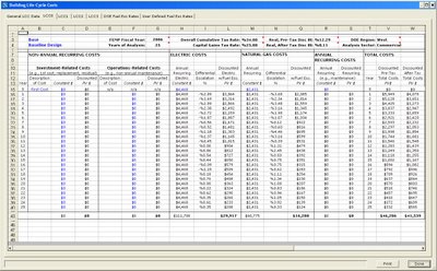
    For the baseline case and each comparative alternative, a lifecycle cost spreadsheet is generated, where comparative costs may be entered:


    If comparative costs are entered, the lifecycle cost report will show the true lifecycle cost comparison of each alternative, including adjustments for energy price escalation based on current DOE projections and the time value of money.

    If no comparative costs are entered as in the following example, the lifecycle cost report shows a "budget" number for each alternative based on projected energy savings:

    Thursday, August 31, 2006

    Qualified Software for Tax Credits

    Topic: Energy-Efficient Commercial Building Tax Deduction under Internal Revenue Service Code 179D. Reference IRS Notice 2006-52 dated June 2, 2006.


    Consultants can help facility owners take advantage of the above tax deductions. As of this writing the qualified software list includes the latest versions of EnergyPlus, Trace 700, and Carrier HAP. There is a rumor on the boards that eQUEST is in in the process of becoming certified.
     

    Wednesday, August 30, 2006

    eQuest Displacement Ventilation

    Topic: What adjustments to the baseline model are required to simulate a displacement ventilation system?

    Energy Design Resources has a reference for doing underfloor and displacement ventilation systems with eQuest. While useful since eQuest (version 3.61 as of this writing) does not yet natively support displacement ventilation, the information is evidently based on an earlier version of eQuest prior to implementation of the 'lighting heat to adjacent space and return air' features shown in the following dialogue (which may be found by doing a 'detailed edit' on spaces in the component tree):

    (click on the image to see a larger version)

    Until eQuest is released with specific displacement ventilation modeling capability, the following workaround may be used to approximate a displacement ventilation simulation solution:
    • Assign a higher fraction of the lighting heat load to the return air for displacement ventilation over the baseline case.
      • If you've accepted the default of 100% lighting heat load to the occupied space for the baseline case, then for example a 50-50 split may be assigned for the displacement ventilation scenario.
    • If there is significant occupant load per square foot, then assign some additional fraction of the lighting load to the return air to account for it, since there is not an explicit option for doing so.
      • Continuing the example above, in school classrooms perhaps a split assigning 70% of the lighting load to the return air is a better approximation for the displacement ventilation scenario.
    • Also adjust supply air delivery temperatures, supply air volumes, and drybulb economizer high limit per the proposed displacement ventilation design; consult with the mechanical engineer.
    • Typically the supply air and drybulb high limit temperatures will be somewhat higher and the overall supply air volume somewhat lower than a baseline overhead distribution system.
    If the project is fortunate enough to be located in a temperate area that does not require mechanical cooling in the spring and fall and is unoccupied during the summer (e.g. a school in western Washington State), then don't expect much in the way of reduced energy consumption. Displacement ventilation can only provide estimable savings by avoiding mechanical cooling.

    Wednesday, August 09, 2006

    Carrier HAP Displacement Ventilation

    Not to be outdone, the folks at Carrier HAP software support also have some recommendations for modeling displacement ventilation systems:

    1. TRACE has a feature that models the return air plenum as a separate space. This lets you define the size of the plenum and heat going into and out of it. The calculate a load for it as if it was a room and also calculate its temperature. The seem to be recommending you use this feature to model the upper stratified zone of the room as a "plenum space" and assign portions of the room loads like lights, etc.. to the plenum space.

    In HAP we don't have an equivalent feature. But you could define a return air plenum and assign part of your lighting, wall and roof loads to the plenum as a way of derating the heat going to the occupied zone in the space. You still need a way to deal with people and plug loads. Perhaps use the schedules to derate these heat gains, or just specify derated sqft/person and W/sqft to begin with. What you'll miss is the portion of these heat gains that goes into the upper zone. And you'll miss the kWh consumption for plug loads if you're doing an energy analysis (could put those back in via miscellaneous energy in the building inputs). Don't know if TRACE lets you put people and office equipment inside a plenum space. Maybe they have a problem with people and plugs too.

    2. On the system side it sounds like they recommend modeling a constant volume AHU that uses a bypass so you have part of the air going thru the cooling coil and part going through a bypass and the two streams mixing downstream. Something equivalent in HAP might be this:

    a. Choose a 3-Deck Multizone system. In cooling mode it mixes neutral (untreated) with cold deck air in the proper proportions to get the proper SAT to meet the load.

    b. Specify the central cooling with 55 F SAT and constant supply temperature control.

    c. You'll want to use user-defined sizing on the sizing tab so you can directly specify the supply airflow. This airflow should be sufficient to meet the peak zone sensible load with a 60 to 65 F supply temperature at the supply diffuser. To figure out what this airflow for 60 to 65 F SAT is to begin with, you may need to run the system once with SAT specfied as 60 to 65 F. Then go back and edit the air system, change the SAT to 55 F and switch to user defined sizing to put in the airflow. Then run calculations a second time. The result is the supply temperature at the diffuser will be 60 F or above, and it will be a mixture of 55 F cold deck air plus untreated neutral deck air.

    We recommend looking carefully at the results like the component loads on the System Design Load Summary and the system operating details on System Psychrometrics to get a feel for whether everything is working the way you intend it to, and is representing what you think displacement ventilation behavior should be.

    Best Regards,
    Carrier HAP Support
     

    Thursday, May 18, 2006

    Trace 700 Displacement Ventilation

    The folks at Trane CDS Support have some suggestions for compelling Trace 700 to do displacement ventilation modeling:

    • The air in a space supplied by an underfloor system is stratified and you only need enough airflow to handle the temperature (loads) in the lower stratified region. Trace (as well as the rest of the simulation programs) assumes well mixed spaces with the same temperature at all locations.
    • They way to handle this is to model the lower portion (the bottom 6 ft or so) as the height in the space. The top portion is then modeled by calling it a plenum space (plenum of about 5 or 6 feet). Then create custom miscellaneous loads and assign a portion of them to the plenum. The same thing can be done with the lights.
    • As for the system side, choose a Constant Volume Variable Temperature system. Go to the Temp/Humidity tab and assign a Leaving Cooling Coil Min and Max temperature of 55°F. Under the Direct/Indirect Humidification Controls, select "CV Mixed Air Bypass with Wild Coil Leaving Temp".
    • This will cause the temp off the coil to be low dewpoint, then air will be bypassed around main cooling coil and reintroduced and mixed back in after the main CC, which will allow the air to be supplied to the space with a reasonable %RH at a higher temperature (60-65°F).

    Wednesday, May 17, 2006

    ELCCA Exchange Kickoff

    The purpose of this weblog is to assimilate and exchange information pertaining to the completion of Washington State Energy Life Cycle Cost Analysis (ELCCA), Washington Sustainable Schools Protocol (WSSP) and Leadership in Energy and Environmental Design (LEED) requirements, from the perspective of the mechanical/electrical consulting engineer.